It is predicted that by 2025 we will interact with a data centre every 18 seconds [1] as our appetite and reliance on the internet continues to grow. This has led to a boom in the electronics industry, with the number of data centres rapidly increasing to keep up with demand. Powering modern electronics, along with data centre servers requires huge amounts of energy and the latest figures show that data centres now consume approximately 3% of the total energy generated worldwide [2].

Thermal management of electronics
However, a large portion of this energy consumption is down to cooling, with some data centres spending 40% of its energy on powering cooling and ventilation systems [3]. This wasted heat needs to be effectively dissipated from electronic devices to avoid damage, maintain performance and improve reliability as well as life.
To try and reduce the amount of cooling required and therefore energy consumption, electronics manufacturers and data centres are exploring new ways of achieving more efficient cooling of electronic components. This will not only minimise energy costs but also their carbon footprint.
Two phase heat transfer
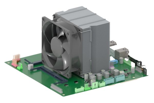
The typical approach to cooling electronics is to use metallic heat sinks that conduct heat away from the heat source via a circulating coolant. However, a much more efficient method of transferring heat is phase change technology. This is essentially where a working fluid absorbs thermal energy as it evaporates, and dissipates this energy as it condenses.
‘Phase change cooling technology is a very effective method of transferring energy at much faster rates,’ explains Dr. Jason Velardo, Thermal Engineer at Conflux Technology. ‘The high latent heat of the working fluid means it requires a large amount of thermal energy to change phase, so it has the capacity to absorb a lot of heat from the source before it evaporates.’
‘Efficient thermal management in electronics is becoming increasingly important as components continue to shrink in size, resulting in more compact and challenging environments,’ continues Velardo. ‘The other benefit to phase change technology is that it is completely passive. It essentially works by itself, unlike conventional cooling systems that need to pump liquid. We would still likely need a fan or pump to move fluid externally to the vapor chamber, but with improvements in performance owing to the vapor chamber we could likely minimise this energy input.’
What is a vapor chamber and how does it work?
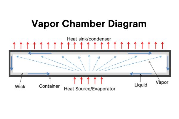
One particular phase change heat transfer devices is a vapor chamber. This two-phase closed loop system consists of a sealed enclosure filled with a working fluid and porous wicking structure. The working fluid absorbs the thermal energy generated from the heat source which causes it to evaporate into a vapor. This less dense vapor rises to a cooler area of the chamber and condenses back into a liquid, releasing the thermal energy as it changes phase.
The liquid then flows through the porous wick structure via capillary action, returning back to the heat source to repeat the process. This constant cycle of evaporation and condensation allows vapor chambers to dissipate heat effectively over large surface areas.
Vapor chamber vs heat pipe
‘Vapor chambers are often compared to heat pipes which are based on a similar phase change principle,’ says Velardo. ‘Heat pipes focus on transferring heat from point A, along a pipe, to point B. Whereas vapor chambers are designed to take heat from a centralised point and spread it across an entire surface. It’s the spreading of heat that vapor chambers really excel at which makes them ideal for managing heat in the concentrated environments of high performance electronics.’
Traditional manufacture of vapor chambers
From the outside, a vapor chamber looks like a flat plate, but inside it is essentially a hollow rectangular container. This container is lined with a porous wick structure which facilitates the movement of the working fluid and inside this is the empty vapor region.
Typically, the container is made from joining machined sheets of metal together. The wick is manufactured separately by depositing layers of powder which are then compacted and heated to create a rigid but porous structure. This wick is bonded to the surface of the metal sheets and the two halves of the assembly are joined together through a metal bonding process.
‘The challenge with these traditional manufacturing techniques is not just that there are so many processes, but that each process requires slightly different temperatures and environments,’ says Velardo. ‘You really have to think about the order of the processes to ensure the structure is joined and sealed securely to avoid any leaks – it can get quite complicated.’
Innovation in vapor chambers: The potential of additive manufacturing
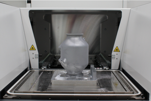
To streamline the manufacturing process, Conflux Technology have been experimenting with using additive manufacturing to print the container, wick and chamber in one monolithic structure using a single printing process. This not only reduces the number of manufacturing stages, but the inherent fidelity of building up a structure layer by layer allows additive manufacturing to create unique shapes whilst maintaining or improving heat rejection performance.
‘It is a fascinating R&D project as there is little research on 3D printed vapor chambers, but we believe it offers huge potential,’ highlights Velardo. ‘One of the main advantages is that it allows us to create highly detailed and intricate designs which would be very difficult to manufacture and seal effectively with traditional methods. This opens up opportunities for using vapor chambers in really challenging environments that previously weren’t possible.’
Unlocking vapor chamber performance
Conflux’s initial vapor chamber design featured a circular shape with an aluminium container and wick, and acetone as the working fluid. After some initial testing, the hydraulic performance of the wick and the thermal performance of the vapor chamber both showed promise:
- The additively manufactured wick had permeability and porosity similar to traditionally manufactured wick structures
- Thermal resistance of the additively manufactured vapor chamber was found to decrease by about 10% over a solid metal thermal spreader
- The vapor chamber also had more uniform temperature distributions on its surface compared to the solid spreader
- Weight reductions of around 50% by switching to the two-phase vapor chamber solution
‘Developing the wick structure was by far the hardest challenge,’ explains Velardo. ‘Since additive manufacturing was invented, the difficulty has been printing solid structures with zero porosity. But the wick structure needs to be porous, so we had to completely reverse our thinking.’
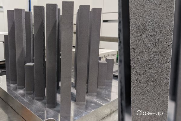
The thousands of microscopic pores within the wick allows the working fluid to pass through it using capillary action. This generates the pressure difference necessary to circulate the condensed working fluid back to the heat source. The characteristics of these pores determine the performance of the wick and therefore its suitability in vapor chambers and other two-phase heat transfer devices.
‘Typically, the most effective wick structures are sintered powdered wick’s,’ explains Velardo. ‘This is where powder is placed in a die, compacted and fused together in an oven, which is a similar principle to Selective Laser Sintering. We wanted to see if we could manufacture a sintered wick using additive manufacturing techniques that have never been done before, and so instead of an oven, we used a laser to partially melt the powder during the print. We can precisely control the behaviour of this laser to fine tune the properties of the wick to achieve higher thermal performance whilst also switching between printing solid walls for the container, and porous walls for the wick,’ continues Velardo.
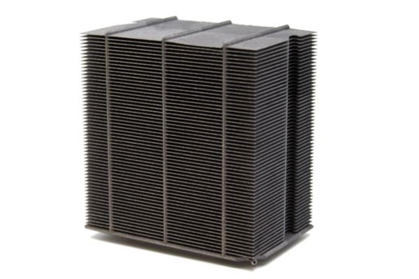
‘Overall, our study showed that additive manufacturing can not only reduce the number of manufacturing processes required for vapor chambers, but also produce vapor chambers with higher thermal performance than conventional designs. There is still further research to be done, but following the success of our R&D work, we have filed several additive vapor chamber patents. The potential benefits additively manufactured vapor chambers can bring to the electronics cooling industry is very exciting.’
References
[1] Data center power consumption [Online]. Danfoss
[2] 2023. What Makes Hyperscale, Hyperscale? [Online]. AFL Hyperscale
[3] 2022. Data Center Cooling Costs [Online]. Dataspan

